- Introduction
- What is Resonance?
- Why is Resonance Important in Electrical Engineering?
- Enhance Your Engineering Precision with Keysight's Certified Refurbished Equipment
- Resonance Frequency Formula
- Derivation of the Formula
- How to Calculate Resonance Frequency: Practical Examples
- Example 1: Basic LC Circuit
- Example 2: Series LC Circuit with Additional Capacitance
- Example 3: Parallel LC Circuit
- Example 4: Adjusting for Desired Resonance Frequency
- Factors That Can Affect Resonance Frequency
- 3 Quick Tips for Managing Variations
- Applications of Resonance Frequency in Electrical Engineering
- Practical Considerations and Safety
- Simulation and Measurement Techniques
- Keysight's Expert-Calibrated Tools
- Transform Your Resonance Frequency Analysis with Keysight's Expert-Calibrated Tools
- Whenever You’re Ready, Here Are 5 Ways We Can Help You
Have you ever thought about creating a circuit that's so efficient it doesn’t waste any energy? Imagine being able to design circuits and systems that sync up with their natural frequency, achieving peak efficiency.
For instance, consider the design of wireless charging systems for electric vehicles. By optimizing the system's components to resonate at the same frequency, engineers can significantly enhance the efficiency of energy transfer from the charger to the vehicle. This reduces waste and speeds up the charging process, making electric vehicles more practical and appealing for everyday use.
Understanding resonance is essential for creating efficient systems. By mastering this formula, you can tune your creations for maximum performance, leading to significant energy savings.
What is Resonance?
Resonance occurs when an object or system oscillates at an amplified intensity when its frequency is completely or partially matched with that of an external force. This concept, foundational in physics and engineering, hinges on the synchronization of vibrational energies, leading to a significant increase or decrease in amplitude.
It’s important to understand that resonance is the condition, not just an increased amplitude; it's when the external force's frequency precisely aligns with the system's inherent frequency, causing the system to oscillate with greater energy.
The physical principles behind resonance result the efficient transfer and conversion of energy within a system at specific frequencies. When a system is driven at its natural frequency, it absorbs energy from the external force more efficiently, resulting in larger oscillations.
It's important to distinguish between natural frequency and resonance frequency, although they often seem interchangeable.
- Natural frequency is an inherent characteristic of a system, the frequency at which it oscillates in the absence of external forces.
- Resonance frequency refers to the specific frequency at which resonance occurs, matching the system's natural frequency when influenced by an external periodic force.
Why is Resonance Important in Electrical Engineering?
Resonance plays an important role in electrical engineering, particularly in the design and operation of various circuits and systems. Its significance is rooted in the ability to enhance or suppress specific frequencies, leading to optimized performance across a range of applications. Here are a few key areas where resonance is especially critical:
- Filters: In the realm of signal processing, resonance is essential for designing filters that selectively allow frequencies within a certain range to pass through while blocking others. This is crucial for applications like radio communications, where it's necessary to isolate specific frequencies from a spectrum of signals.
- Oscillators: Resonance supports the functioning of oscillators, which generate a continuous output of a specific frequency. This is fundamental in creating stable signals for clocks, radios, and computers, where precise frequency control is necessary.
- Transmission lines: Understanding resonance is important for signal integrity in transmission lines. It ensures that signals can be transmitted efficiently over long distances without significant loss, which is important in telecommunications and power distribution networks.
The concept of resonance in AC circuits introduces a fascinating aspect of electrical engineering. Here, resonance occurs when the inductive and capacitive reactances in a circuit balance each other out. The result is a circuit that behaves as resistive at the resonance frequency.
This principle leads directly to the resonance frequency formula, which is important for designing circuits that operate efficiently at desired frequencies. By manipulating elements within an AC circuit to achieve resonance, engineers can improve circuit performance, minimize energy losses, and ensure stability in their designs.
Enhance Your Engineering Precision with Keysight's Certified Refurbished Equipment


Resonance Frequency Formula
The formula for calculating resonance frequency in LC (inductor-capacitor) circuits is:
f = 1 / (2π√(LC))
Here's a breakdown of each component in the formula:
- f represents the resonance frequency, measured in Hertz (Hz)
- L is the inductance of the coil, measured in Henries (H)
- C is the capacitance of the capacitor, measured in Farads (F)
- π is a mathematical constant, approximately equal to 3.14159
This formula highlights how the inductance (L) and capacitance (C) in a circuit determine its natural oscillation frequency at resonance. Let’s dive into each component:
- Inductance (L) shows the conductor’s ability to store energy in a magnetic field. A higher inductance value means more energy can be stored, which has an inverse effect on the resonance frequency, leading to slower circuit oscillations.
- Capacitance (C) reflects the capacitor's ability to hold energy in an electric field. Similar to inductance, a larger capacitance results in a lower resonance frequency, slowing the rate of oscillation.
- The constant 2π is derived from the mathematical relationship that connects circular motion and oscillation, linking the circuit's physical properties to its behavior in oscillating.
Derivation of the Formula
Deriving the resonance frequency formula for an LC circuit involves understanding how inductance and capacitance interact in an electrical system. Let's break down this derivation into clear, simple steps:
- Start with the basics: An LC circuit consists of an inductor and a capacitor connected together. When energy is supplied, it oscillates between the inductor's magnetic field and the capacitor's electric field.
- Understand natural oscillation: The system naturally oscillates at a frequency where the energy in the inductor equals the energy in the capacitor, leading to resonance. This frequency is determined by the properties of inductance and capacitance.
- Apply Kirchhoff's voltage law: In a closed circuit, the sum of voltage drops (V) equals the supplied voltage. For an LC circuit at resonance, the voltage across the inductor equals the voltage across the capacitor but in opposite phases, canceling each other out.
- Use the relationship between inductance, capacitance, and frequency: The oscillation frequency can be found by analyzing the circuit's impedance, leading to the formula: frequency (f) is the inverse of 2π times the square root of the product of L and C.
- Finalize the formula: Simplifying the relationships and constants leads us to the resonance frequency formula, which is fr = 1 / (2π√(LC)).
This formula directly connects the circuit's physical characteristics (L and C) to its resonance frequency, allowing you to predict and control the behavior of LC circuits.
How to Calculate Resonance Frequency: Practical Examples
Understanding how to calculate resonance frequency through practical examples illustrates the versatility of the formula: f = 1 / (2π√(LC)) across various circuit configurations. Here are several examples:
Example 1: Basic LC Circuit
Imagine you have an inductor of 10 millihenries (mH) and a capacitor of 100 microfarads (µF). To find the resonance frequency:
- Convert values to standard units: L = 0.01 H, C = 0.0001 F
- Plug the values into the formula: f = 1 / (2π√(0.01*0.0001))
- Calculate: fr ≈ 159.15 Hz
This circuit would resonate at approximately 159 Hz, meaning it would naturally oscillate at this frequency when energized.
Example 2: Series LC Circuit with Additional Capacitance
Consider a series LC circuit with an inductor of 5 mH and two capacitors in series, each of 200 µF. The effective capacitance of two capacitors in series is given by 1/\(C_{eff}\) = 1/\(C_{1}\) + 1/\(C_{2}\), where \(C_{1}\) and \(C_{2}\) are the capacitances of the individual capacitors.
- Find the effective capacitance: \(C_{eff}\) = 100 µF
- Convert to standard units: L = 0.005 H, \(C_{eff}\) = 0.0001 F
- Calculate resonance frequency: f = 1 / (2π√(0.005*0.0001)) ≈ 225.08 Hz
Example 3: Parallel LC Circuit
If an LC circuit is designed with an inductor of 20 mH and a capacitor of 50 µF in parallel, and you want to find its resonance frequency:
- Convert to standard units: L = 0.02 H, C = 0.00005 F
- Use the formula: f = 1 / (2π√(0.02*0.00005))
- Calculate: f = 159.15 Hz
Example 4: Adjusting for Desired Resonance Frequency
If you need a circuit to resonate at 200 Hz and you have a capacitor of 100 µF, what inductance is required?
- Rearrange the formula to solve for L: L = 1 / (4π²f²C)
- Plug in the values: L = 1 / (4π²*(200)²*0.0001)
- Calculate: L = 6.366e-3 H or approximately 6.37 mH
Factors That Can Affect Resonance Frequency
The resonance frequency of a circuit is not a fixed value and can be influenced by a variety of factors, both internal and external. Understanding these variables is crucial for accurate circuit design and testing:
- Changes in inductance and capacitance: Any modification in the values of inductance (L) or capacitance (C) directly affects the resonance frequency, as seen in the formula: fr = 1 / (2π√(LC)). For example, replacing a capacitor with one of a different capacitance will alter the circuit's resonance frequency.
- Physical dimensions: The physical size and shape of the components can impact their inductance and capacitance values. For instance, a longer coil or a larger capacitor plate area typically increases inductance and capacitance lowering the resonance frequency.
- Temperature: Temperature changes can cause physical expansion or contraction of materials, affecting the inductance of coils and the capacitance of capacitors. Higher temperatures might decrease the inductance of coils due to increased resistance and alter the dielectric properties of capacitors, affecting their capacitance.
- Humidity: Increased humidity can affect the dielectric properties of materials used in capacitors, potentially increasing capacitance and thus lowering the resonance frequency.
3 Quick Tips for Managing Variations
- Compensation: Include variable components (e.g., varactor diodes for capacitors, variable inductors) in your design to adjust and compensate for unwanted changes in resonance frequency.
- Environment control: Test circuits in controlled environmental conditions to minimize the effects of temperature and humidity.
- Quality equipment: Use high-quality components with low tolerance values to ensure minimal deviation in inductance and capacitance, leading to a more stable resonance frequency.
Understanding these factors and planning for them in the design and testing phases is essential for achieving accurate and reliable circuit performance. Quality equipment and thoughtful circuit design can mitigate the impact of these variables, ensuring that the resonance frequency remains as close to the desired value as possible.

Applications of Resonance Frequency in Electrical Engineering
Resonance frequency finds its applications across a broad spectrum of electrical engineering disciplines, showcasing its versatility and critical importance. From traditional uses in telecommunications and power systems to innovative applications in medical devices and emerging technologies, the principles of resonance frequency shape the future of engineering solutions.
- Telecommunications: In telecommunications, resonance frequency is fundamental for filtering and tuning circuits to specific frequencies. For instance, resonant circuits are used to select the desired channels in a radio receiver, allowing it to isolate signals at a particular frequency from a mix of different signals.
- Power systems: Resonance is critical in the design of transformers and power transmission lines. It helps in optimizing the power transfer efficiency and minimizing energy loss. Inductive power transfer systems, such as those used for wireless charging of electric vehicles, rely on resonance to efficiently transfer energy over a gap without physical connections.
- Medical devices: Resonance frequency is used in medical imaging technologies, such as Magnetic Resonance Imaging (MRI). By matching the magnetic properties in the body to the frequency of the applied radio waves, MRI machines can create detailed images of internal structures, aiding in diagnosis and treatment.
- Wireless charging: One of the most innovative applications of resonance frequency is in wireless power transfer. Devices like smartphones and electric toothbrushes are charged wirelessly using resonant inductive coupling. This method enhances the transfer efficiency over distances, making wireless charging more practical and widespread.
- Signal processing: Resonance is used in signal processing to enhance or suppress specific frequency components of a signal. This is vital in applications ranging from music production to seismic data analysis, where filtering out unwanted frequencies can clarify or isolate important information.
Future Potential
The future of resonance frequency in electrical engineering promises even broader applications, particularly as we explore emerging fields like quantum computing and nanotechnology.
In quantum computing, resonance frequencies could help in precisely controlling qubit states, leading to more stable and powerful quantum computers.
In nanotechnology, resonance principles are being explored for new materials and sensors, enabling advancements in environmental monitoring, healthcare, and material science.
Practical Considerations and Safety
Working with circuits at resonance demands careful attention to safety and practical considerations due to the potential for high voltage and current. These heightened levels can not only damage the circuit components but also pose serious safety risks to individuals.
- Safety concerns: At resonance, circuits can experience significantly increased voltage and current, leading to the risk of electrical shock or component damage. Always use components rated for higher voltages and currents than expected at resonance.
- Component heating: The increased current can cause components, especially inductors and resistors, to heat up. Ensure adequate cooling and ventilation in the circuit design to prevent overheating.
- Unexpected oscillations: Resonant circuits can sometimes oscillate at unexpected frequencies, potentially causing interference with other equipment. Incorporate frequency-limiting measures and shielding to mitigate this issue.
Troubleshooting Techniques
When encountering issues with resonant circuits, here’s a quick reference table for common problems and solutions.
| Common Problems | Solutions |
|---|---|
| Circuit not reaching resonance | Check component values and connections. Verify that the inductance and capacitance are correctly calculated and matched. |
| Overheating components | Ensure components have adequate power ratings. Improve cooling and ventilation. |
| Unexpected oscillations | Implement frequency stabilization techniques, such as damping resistors or additional filtering. |
| High voltage causing damage | Use voltage limiters or protective diodes. Ensure the circuit is designed with components rated for the expected voltages. |
Design and Handling Tips
- Precautionary measures: Always disconnect power before making changes to the circuit. Use insulated tools to prevent accidental contact with live components.
- Component selection: Choose components with appropriate ratings for voltage, current, and power. This prevents failure and ensures the longevity of the circuit.
- Testing and measurement: Use oscilloscopes and multimeters to monitor voltages and currents closely, particularly when approaching resonance. This helps to identify and mitigate risks in real time.
Addressing these safety concerns and practical considerations ensures not only the effective performance of resonant circuits but also the safety of those working with them. Proper planning, component selection, and vigilance in monitoring are key to navigating the powerful potential of resonance safely and effectively.
Simulation and Measurement Techniques
In electrical engineering, accurately predicting and measuring resonance frequency is pivotal for optimizing circuit performance and ensuring reliability. A blend of simulation tools and measurement techniques equips engineers with the insights needed to fine-tune their designs for maximum efficiency.
Simulation Tools and Software
To anticipate the behavior of electrical circuits, including resonance phenomena, engineers turn to several sophisticated simulation tools and software packages:
- SPICE (Simulation Program with Integrated Circuit Emphasis): A widely used open-source simulation tool for predicting the electrical behavior of circuits.
- ANSYS Electronics Desktop: Provides comprehensive electromagnetic, circuit, and system simulation tools, making it ideal for complex analyses.
- LTspice: A high-performance simulation software that enhances the ease of analog circuit simulation.
These simulation platforms allow for the modeling of circuit behavior under various scenarios, helping engineers to identify and mitigate potential issues early in the design process.
Measurement Techniques
For real-world verification, oscilloscopes, frequency analyzers, and network analyzers are indispensable tools in identifying resonance frequency.
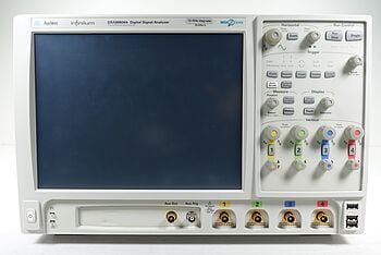
- Oscilloscopes: These devices visualize voltage changes over time, providing a snapshot of the circuit's behavior at different frequencies. By changing the frequency of the signal going into the oscilloscope and watching how the voltage level goes up and down, engineers can find the resonance frequency where the voltage reaches its highest point.
- Frequency Analyzers: These are specialized tools designed to measure the frequency of a signal accurately. They can directly display the resonance frequency by analyzing the circuit's response to a range of frequencies.
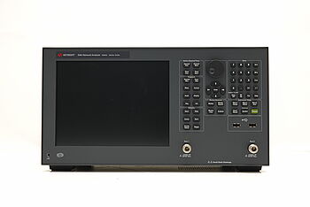
- Network Analyzers: Crucial for measuring the network parameters of electrical networks, network analyzers can provide detailed information on resonance by assessing parameters like S-parameters, which reflect gain, loss, and reflection in circuits.
| Measurement Device | Pros | Cons |
|---|---|---|
| Oscilloscope | High temporal resolution, visualizes waveform changes over time. | May require complex setups for accurate frequency measurement. |
| Frequency Analyzer | Directly measures frequency with high accuracy. | Typically more expensive than oscilloscopes. |
| Network Analyzer | Can measure both magnitude and phase, essential for detailed resonance analysis. | Complex and expensive, best suited for advanced applications. |
Keysight's Expert-Calibrated Tools
Keysight Technologies stands out for its range of premium used measurement tools. Known for their precision and reliability, Keysight's calibrated tools, such as network analyzers and oscilloscopes, offer unparalleled accuracy in resonance measurement and analysis.
By leveraging advanced simulation tools and precision measurement equipment, engineers can navigate the complexities of resonance in electrical circuits, improving both the development process and the performance of the final designs.
"For all used equipment, I offer my clients calibration and 1-year warranty." – Keysight Account Manager
Transform Your Resonance Frequency Analysis with Keysight's Expert-Calibrated Tools
Exploring resonance frequency has shown us how to improve circuit efficiency and minimize energy waste. We learned about calculating resonance frequency, highlighted the significance of safety in engineering, and showcased how tools like oscilloscopes and frequency analyzers are key in identifying resonance in circuits.
We are committed to helping you make efficient circuits not just a dream but a reality. With our precision tools, hitting the resonance frequency accurately becomes part of your everyday work. Keysight is here to support your journey towards more efficient and innovative circuit design.
Whenever You’re Ready, Here Are 5 Ways We Can Help You
- Browse our premium used network analyzers, oscilloscopes, signal analyzers and waveform generators.
- Call tech support US: 1 800 829-4444
Press #, then 2. Hours: 7am – 5pm MT, Mon– Fri - Talk to our sales support team by clicking the icon (bottom right corner) on every offer page
- Create an account to get price alerts and access to exclusive waitlists
- Talk to your account manager about your specific needs